Some recommendations about use of low-frequency electromagnetic transmitters and locators for tracking of in-line PIGs during pipeline cleaning or inspections
It is known that alternating with low frequency magnetic field is not shielded much by metallic wallsof a pipeline (if compared with high-frequency alternating field). So devices which are capable to register low-frequency oscillations of magnetic field are widely used for pipelines cleaning and inspections. With help of these devices it is possible to find the place where (utility or smart PIG has stuck in the pipe.
Typically a generator of low-frequency electromagnetic waves (called transmitter) is attached to a PIG, which is moving inside the pipe by the flow of transported oil or gas. A very sensitive low-frequency receiver (called also as locator) is then used to receive this signal from above the ground covering up the pipeline.
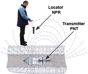
The accuracy of the transmitter detection and maximum possible distance from the pipeline for this detection depends from several factors such as: circuit and design technology used in the devices, thickness of metallic walls, the frequency of magnetic field oscillations.
The less is the thickness of the metallic walls as well as the lower is the frequency of oscillating magnetic field then the less is power, which should emit the transmitter. And hence the less is emissive power then the longer this transmitter can autonomously work due to internal power supply.
The time of transmitter autonomous work is a critical parameter for inspection or cleaning of long pipelines. And the length of currently used pipelines is often several hundred kilometers. It takes several days for a pig with the transmitter to go through such a pipeline.
It is not possible to change the thickness of walls in a pipeline. While it is the frequency of emitted signal, which designer of the device can change. The upper and lower borders of the frequency range are determined by the following considerations (and there is always a compromise between different requirements):
As it was already mentioned that the lower is the signal frequency then the less signal is weakened (by metallic walls and by soil). However the lower is the frequency the more difficult it is to extract useful signal from the transmitter against the background of electromagnetic noises. I.e. more time is necessary for this extraction. And some noises ( caused by different industrial electric motors, pipeline cathode current protection, etc) always exist.
So if an in-line PIG with the transmitter is moving in the pipe with velocity of several meters per second then the reciever might not have enough time to register the passage in the case when the frequency of emitted signal is too low. It means the receiver will fail to detect the transmitter attached to the PIG.
Also for very low-frequency (almost static magnetic field) the residual scattered pipe magnetization (after passage of a smart or utility PIG with strong magnets) as well as magnetization by Earth magnetic field can act as a noise.
From the other hand ncreasing of the frequency leads to loss of emitted signal power. And when the frequency of emitted signal approaches 50Hz (industrial frequency) then the noise level increases considerably.
Keeping all these considerations in mind designers typically chose the frequency for transmitter and receiver from the range of 10 to 30 Hz. 22 Hz is the mostly used optimal frequency for pipeline inspections.
The choice in favor of 22Hz frequency is dictated also by the fact that in development of a new device it is necessary to remember about compatibility with devices of previous versions. Also a transmitter manufactured by one firm can be used for work with receiver manufactured by other firm.
One of the problem, which is commonly faced by a user of low-frequency transmitters and locators is the problem to receive a confirmation from the device manufacturer that signal from the transmitter (installed on particular PIG) will be detected by a ground-based low-frequency locator in all points along the pipeline. This question is usually asked about the parts of the pipeline where the wall thickness is maximal or where the pipeline is located rather deep underground (buried pipelines).
Why this question is so difficult to answer? Well, because there are many factors influencing signal detection by locator in the conditions of electromagnetic noises of different nature. Among these noises there are: working electric motors; an electricity transmission line located nearby; not optimal emission conditions when the transmitter is not properly installed on the PIG.
Weakening of signal strength in the last case might be caused by metallic ferromagnetic parts of the PIG, which the transmitter is attached to. In this case the parts shield the signal from the transmitter.
The problem about confident detection of the signal in any point of the pipeline can be partially resolved by a test described below.
It is necessary to attach the transmitter to the PIG and then to measure maximum distance in the air between the locator and the transmitter. It is so called distance "in air" (when there are no obstacles or noises influencing the signal detection).
Using the chart shown on Figure 1 below and knowing maximum distance in the air as well as the pipeline wall thickness it is possible to determine detection distance for the transmitter inside the pipeline.
This value would be a maximum distance from which the transmitter will be detected by particular locator in real conditions (i.e.when the transmitter is attached to the PIG and signal is weakened by the pipeline wall).
Figure1. A graph for determination of maximum distance at which a locator can detect a transmitter when its signal is weakened by pipeline metallic wall.
Let's consider an example shown on Fig.1 by blue arrows. Suppose a transmitter installed on an in-line PIG is detected by a locator from the distance 25m in air (i.e. there is no weakening of the signal by pipeline). Now suppose this PIG with the transmitter is moving inside a pipeline with pipe wall thickness 15mm. In this case the locator will be able to detect transmitter's signal from the maximum distance 10m.
Magnetic field pattern from a transmitter resembles in the first approximation a magnetic dipole. Magnetic field lines for transmitter are shown on Figure 2. Calculations have shown that intensity of such field drops proportionally to the distance in fourth power. It is very rapid reduction of intensity. Contemporary transmitters are detected by locators (in the absence of weakening by a metallic wall) from distance of about 20-30 meters in the air.
Theoretically this distance can be increased by narrowing of the resonance curve of the transmitter and locator. I.e. by increasing the quality of the resonating electric circuit and making the resonance curve more sharp it is possible to reach bigger distance in the air.
However later such transmitter with very narrow resonance curve is installed inside of an in-line PIG (different shapes and dimensions exist) and then launched trough a pipeline (different pipe thickness and diameters exist and typically are not known for manufacturer of the transmitter).
So due to variations of total inductance of the magnetic system (transmitter+PIG+pipeline) the resonance frequency detune is inevitable. And practical detection distance for locator-transmitter system which could be excellent in the air can be bad in pipeline. That is transmitters with very sharp resonance frequency curve would be detected by a locator outside the pipeline worse than transmitters with "smeared" resonance frequency.
So there is an optimum between maximum detection distance of a "naked" transmitter in the air (i.e. test conditions) and the detection distance for the same transmitter installed inside a PIG, which is moving inside a pipeline (i.e. in real working conditions). And only distance in real working conditions is important for the operator who uses these devices in the field.
Next important moment is the correct attachment of the transmitter on a PIG.
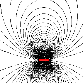
Figure.2 Signal from a transmitter in the air is a signal from magnetic dipole
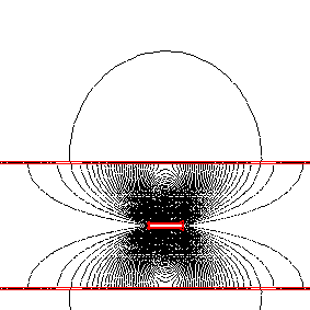
Figure.3 Transmitter magnetic field signal weakened by pipeline metallic wall
The reason is that metallic wall of a pipeline tend to close considerable part of magnetic filed lines to themselves (see Figure 3). In practice a signal coming from a transmitter which is inside a pipeline with wall thickness 20mm can be detected by a locator from distance not exceeding 8m (see also Figure 1). This circumstance have to be taken into account for planning of inspections or cleaning for deeply buried pipelines.
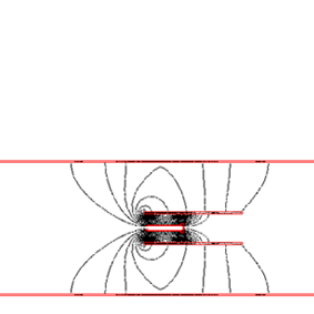
Figure.4 Not correct transmitter installation completely inside PIG's metallic body weakens signal dramatically
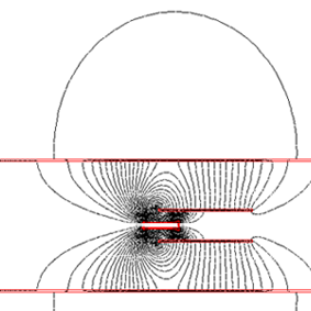
Figure. 5 Signal from a transmitter which is correctly half length out from the PIG's body is not weakened
The magnetic field lines are even more closed (so less part of them will go out of the pipeline) if a transmitter is installed completely inside metallic body of a PIG. Such installation is not correct (see Figure 4). Because the signal from such installed transmitter will hardly left a pipeline. And it will be very difficult to detect it by a locator.
So for correct installation of a transmitter in a PIG with metallic body at least half of the transmitter length should be out of metallic body of the mandrel PIG.
When a transmitter is installed correctly then the body of the PIG starts working as a lengthener for the dipole (see Figure 5). And the detection distance for the transmitter is increased.