About methods and devices which enable to increase quality of gas pipelines inspection
Accidents on the gas pipelines
It is not the first time when mass media report about severe accidents happening on the gas pipelines with medium and low pressure.
Events description during the explosion of gas pipeline in Moscow city, which happened 10 of May 2009, looks like news from a local war:
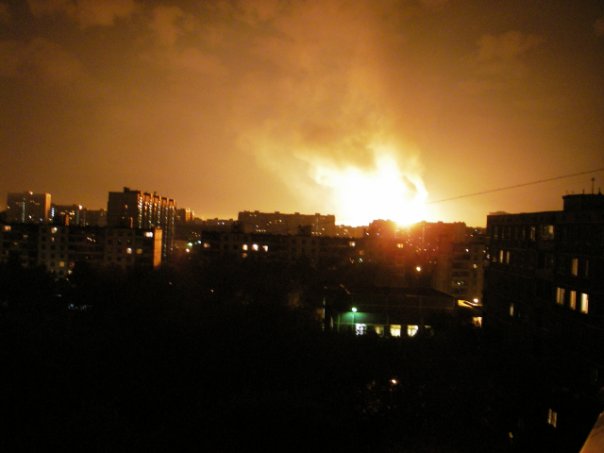
According to the information from Mosgaz, particularly:
It was a middle pressure gas pipeline, which exploded in Moscow 10.05.2009. Such pipelines carry the gas from main transportation pipelines to the distribution station and then gas is distributed to the final consumers.
Possible causes of the accident
Defects of the pipeline walls (which were not detected during in-line inspections) could be the reasons of the pipeline destruction. And fire which followed was the consequence of this pipe destruction.
Unlike oil pipelines the inspection (defectoscopy by an MFL tool) for gas pipelines of middle and low pressure is quite challenging process due to certain technical problems. And the main problem is non-smooth motion of the utility and inspection PIGs in the compressible gas media transported in the pipeline.
Moving by jerks the inspection PIG (magnetic-field flaw detector) is not able to collect reliable data about defects on the pipe walls.
A typical graph of motion for MFL PIG inside gas pipeline with low pressure and small rate of gas flow is shown on the Fig.1 below.
Fig. 1 Motion of Diagnostic Pig Inside Gas Pipeline
1 - motion velocity according to the on-board odometers (in peaks the speed is 7.5 m/s and higher); 2 - allowable range of velocity for reliable inspection of a defect (maximum 2 m/s); X axis - distance passed by the PIG (meters). Y Axis - speed of the inspection PIG (meters per second).
On this graph it can be seen that the motion of the inspection PIG in the gas pipeline (with low pressure and small rate of gas flow) happens with multiple stops and following jerks. Detailed analysis reviled that the stops occur in the places of different narrowing in the pipe.
The PIG stops even on insignificant narrowings such as circumferential welds. The PIG will start moving again only after some additional gas pressure is accumulated behind the it. And after the PIG started moving whole potential energy of compressed gas (on a significant length of the pipe) transforms into kinetic energy of the PIG motion. The PIG accelerates and gains considerable speed. It decelerates only after some period of time.
As a result inspection PIGs pass considerable pipe sections with the velocity, which exceeds maximum allowable velocity for reliable gathering of information about defects in the pipe walls.
Modern Methods for Gas Pipeline Inspections
At present the inspection of gas pipelines is generally performed using magnetic-field flaw detectors (sometimes briefly called magniscans or MFL pig). For reliable detection of defects the maximum speed of motion for such devices should not exceed some value because of certain physical phenomena.
_from_ppsa.jpg)
The point is that during inspections with MFL pig it is necessary to magnetize (up to saturation) a certain section of the pipe by means of permanent magnets. Simultaneously special sensors are pressed to the magnetized metallic wall in order to measure magnetic field strength in the very vicinity of the wall surface.
The magnetic field strength depends on the thickness of the wall below the sensor. At defects the thickness is smaller and the sensors register alterations of magnetic field strength. Signals from all magnetic sensors are recorded into the inspection PIG internal memory with certain discreteness.
The position of defects (such as cracks, pitting corrosion, etc.) is then determined during computer based interpretation of the recorded information. This information analysis enables to select the most risky sections of the pipeline and repair the pipeline properly.
However when inspection PIG moves fast then it is not possible to record signals from the sensors with sufficient discreteness. Moreover the sensors bounce-off from the pipe wall due to circumferential welds and other ruggedness and obstacles.
So the probability to miss a defect is higher for those sections of the pipeline where the inspection PIG moves with the speed exceeding the maximum speed allowable by particular technology.
In-line PIG motion with jerks is the main reason of poor quality of defects detection in gas pipelines.
he jerkiness of a PIG motion inside gas pipelines is due to the following reason: When a PIG stops at a narrowing in a gas pipeline then the pressure behind the PIG starts to increase. The pressure difference is growing until its action on the PIG is less than static friction force (acting from pipe walls on the PIG). When the pressure difference exceeds this starting friction then gas acting like a spring "shoots" the PIG out from this narrowing.
As a result the sections of gas pipeline located directly after the narrowings (and after other obstacles) remain poorly checked for dangerous defects from inspection to inspection for years.
This problem is much more dangerous for gas outlets (i.e. for gas pipelines with low and medium pressure which are supplying gas to final consumers) rather than for oil pipelines. And it is less actual for transit gas pipelines with high gas pressure and high gas flow rate. I.e. the less is compressibility and higher density of transported media the less is probability that inspection PIG will move with jerks.
For traditional utility and inspection PIGs (piston like design) the smooth motion (without jerks) in the gas pipelines is not possible. And speed instability (jerks) inevitably cause the loss of inspection data on many sections of the gas pipeline.
As result the in-line inspection of medium pressure gas pipelines conducted by inspection PIGs of conventional (piston like) design cannot guarantee a reliable collection of the information about defects. So following estimation of the pipeline strength made in a computer program cannot be accurate.
Under the circumstances the probability of accidents on the gas pipelines is high and unfortunately is going to grow (as the pipelines became older).
At this time the completeness of the inspection information is the key factor of safe exploitation of a pipeline. It is based on the estimation of current state for particular pipeline and its parts received during in-line inspections. Such approach (i.e. estimation of current state safety) is officially accepted in Russia and in other countries.
The main conclusion is that it is necessary to limit maximum speed of a PIG motion during gas pipeline inspection.
It has been proposed recently to reduce maximum speed of in-line PIGs and reduce speed instability by installing a bypass. In-line PIGs with electronically controlled bypass are already used for transit gas pipelines inspections.
In the PIG equipped by the bypass there is a central channel with a restriction inside it, which consists of several valve flaps. The position of the flaps in the channel is controlled by an electronic unit. When the flaps are not completely closed then some part of gas will flow through the bypass and the PIG will move more slowly (i.e. slowly then the speed of gas transportation).
However this system has some restrictions, which reduce its efficiency for inspection of gas pipelines with medium and low gas flow rate. The reason is that for a PIG with bypass the same pressure difference is necessary to go through a narrowing in the pipe as for a PIG with conventional (piston like) design.
Simply because the polyurethane carrying discs or cuffs can squeeze through the narrowing only if certain force is applied. This force is equal to the pressure difference multiplied by the pipe cross-section area.
So after the PIG with bypass leaves the narrowing the accumulated pressure will inevitably accelerate this PIG. Because even if the electronics (which controls the flaps) will react instantly and give a command to open the bypass channel completely nevertheless some time will be necessary for the flaps to perform this mechanical action (displacement of the flaps) and indeed to open the channel and to relieve (to drop) the pressure.
During this time the PIG will gain the speed.
Conception of Active Piston consists of effective use of the energy contained in the gas transported via a pipeline.
Aprodit Ltd propose to smooth the speed of an in-line PIG and make it more stabile by more effective way. In this method every time the PIG approaches a narrowing in the pipe its polyurethane discs (cuffs) starts to move.
Moving by special way the cuffs push the PIG. And it "squeezes" through the narrowings (70% from nominal diameter) very smoothly. The cuffs start moving only when the PIG slows down or stops in a narrowing.
In this case the pressure behind the PIG with active cuffs exceeds some limit and it sets a gerotor mechanism (connected with the cuffs) in motion. So the energy comprised in the transported gas flow is used smartly to perform the work for moving the PIG through the narrowing.
The method of using active cuffs as an engine is patented: Invention №2008148176 "A method to move an apparatus through the pipe and the device for realization of this method (and its variants)".
Due to the cuffs active motion the passage of a narrowing takes less time. And the big pressure difference is not accumulated. So the PIG is not accelerated after it leaves the narrowing.
In the patented method there is no need for using of electric batteries or accumulators for controlling the speed of motion. The work for cuffs motion is taken directly from potential and kinetic energy of transported gas.
In case if the mechanical system moving the cuffs breaks down then the PIG will continue the motion through the gas pipeline as a PIG with conventional piston like design.
Industrial application of the PIG with Active Cuffs will raise the quality of gas pipeline outlets inspection.
APRODIT designed and manufactured a prototype of the cleaning PIG with movable active discs for the pipe of small diameter (150 mm). This prototype includes low-frequency transmitter (which enables to find the pig in a gas pipeline with metallic walls).
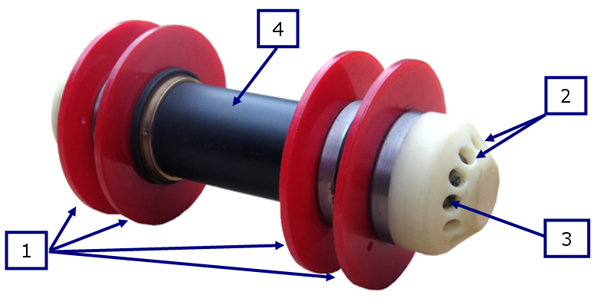
Fig. 2 Cleaning Pig with Active Cuffs and Transmitter
1 - Polyurethane disks (movable); 2 - Holes (channels) for gas flow; 3 - Gerotor mechanism (inside central channel); 4 - Transmitter PNT-04 (inside the PIG body).
This prototype model was tested in a test stand made of transparent glass pipes of 150 mm (6 inches) diameter.
In this stand there are tree typical pipeline narrowings which are the most difficult obstacles for a PIG to pass.
- Partially closed ball cock (globe valve)
- Pipe bend 90 degree with R=1.5xD made of 3 segments
- T-joint with lower location of the branch pipe
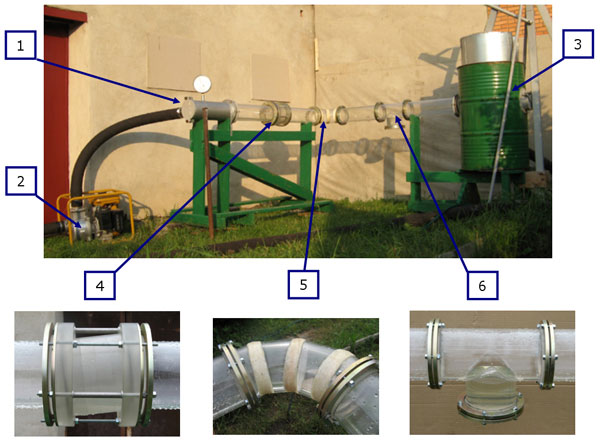
Fig. 3 Test stand made of transparent glass pipes 150mm diameter
1 - Launcher; 2 - Pump; 3 - Displacer; 4 - Partially closed ball cock; 5 - Bend ; 6 - T-joint.
The prototype passed all the stand narrowings. The mechanical system with active cuffs worked in normal mode and exactly as it was designed. A video report about the test can be watched on You Tube.
Aprodit is now looking for an investor for industrial development of the devises with such active cuff system. Due to their good passing ability the PIGs with active carrying structures (discs, cuffs, brushes) can be used not only in gas pipelines but also in other kind of pipe ducts where the application of PIGs with piston like design is complicated or is not effective.
Wide implementation of devices with active cuffs (also disks or brushes) will increase the quality of gas pipelines inspection.So their exploitation will be more safe. It means that it will be possible to avoid accidents like one, which happened in Moscow in May 2009. Commercial production of devices with active cuffs will enable to take market niche for non-transit gas pipelines inspection.
Should you have any questions or proposals concerning active cuff PIG or other possible applications which need movable cuffs then don't hesitate to contact us.